
Back to everyone’s favorite task, wiring up the track. Admit it, now that you’ve been through the planning process it’s not so scary – right? Well even so, remember to invite your wiring buddy from the Club and have some refreshments on-hand. The work will go quickly.
Before continuing with the wiring, it is important to get the power pack and turnout controllers placed, attached to the layout, and the holes predrilled for the wires. Remember those big Kato connectors? To avoid drilling huge holes I cut the connectors off the wires, leaving about a foot of wire still attached. That let me feed the wire through the hole from the top of the layout, and then create the splice under the layout. The only “big hole” I drilled was for the power plug from the wall-wart transformer. I wanted to be able to unplug it, fish it back through the hole and out so the transformer could be packed away during layout storage.
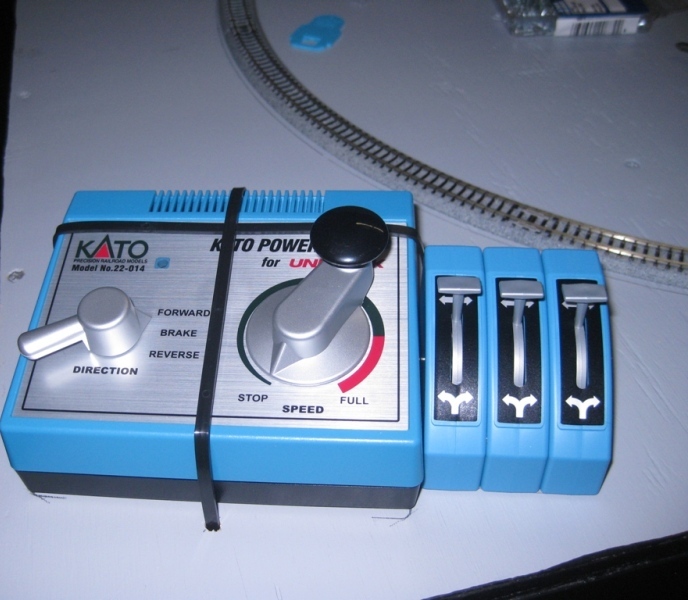
 Attaching the power pack to the layout required the use of cable tie wraps, because Kato didn’t include any mounting holes on the bottom, nor could it be disassembled so I could drill holes. Kato did, however, include keyholes on the bottom of the turnout controllers. Too bad they didn’t full grasp the way keyholes are supposed to work (see photo below).
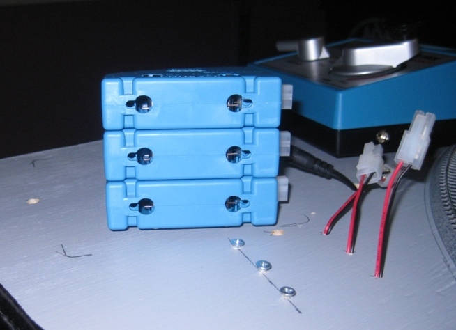
I compensated by using a single keyhole/screw at the front of each controller, and double-sided sticky tape along the bottom to stick it down to the layout surface. I also crisscrossed the power pack with black cable tie wraps (as discussed above) to secure everything down.
 The next photo shows the back of the equipment, with the various connectors/wires routed through the layout top. Nothing has been connected up underneath yet, that comes next.

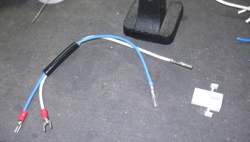
Here we see the extra wiring components that I purchased from my favorite online electronic parts house, All Electronics. We’ve got color-coded hookup wire (blue and white for track power, red and black for turnout controllers), screw-terminal strips for use at the module joints (shown are only the 2-terminal size, I ended up using some 4-terminal as well), and the Molex connectors that would be used to create the pigtail jumpers that actually connect the wires across the joints.

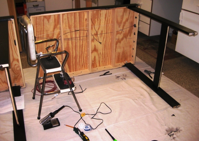
For the past 25 years or so I suffer from dizzy spells caused by Benign Paroxysmal Positional Vertigo, a sudden sensation that the inside of my head is spinning, as well as the room. It most often occurs when looking up for long periods of time, or cocking my head to one side. It can be annoying when wiring a layout, so whenever possible I wire my modules while lying on their side, as shown below. While I can’t always do this, it does make it much easier to wire – with much less “excitement.” Here I’m in the process of wiring the right-hand module. It has power feeder TJ5 and turnout T2. If you look closely you’ll see the two-wire power bus running from one end of the module to the other. You can also see the splice in the turnout control wiring in progress.
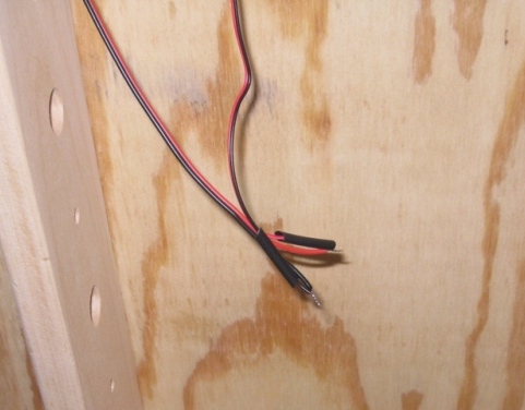
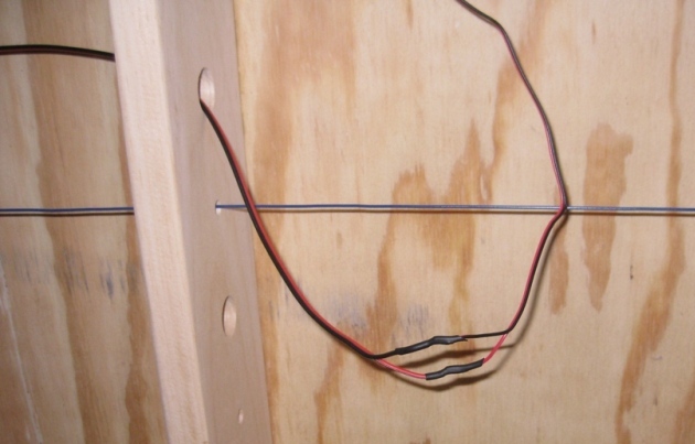
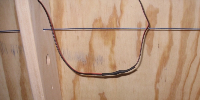
Splicing two wires together, in this case the red/black turnout control, isn’t too difficult if you remember to plan ahead. It helps to remember to slip the heat-shrink insulation over the wires BEFORE you solder them. I can’t tell you how many times I’ve forgotten that and had to cut the wires and start over. In this case I have two layers of heat-shrink; a small diameter layer to insulate the solder joints; and a larger diameter layer to slip over both wires and completely hide the joints. This is shown in the three photo sequence below:
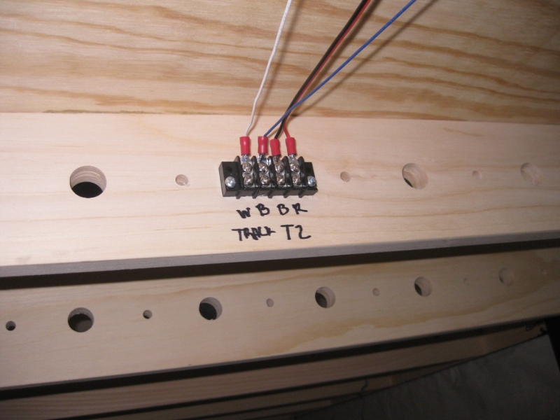
Remember what I mentioned about documenting your work? That applies to not only the original wiring plan, but the installed wiring as well. Here is a quick photo of that documentation. ‘TRACK’ power is on the left, using ‘W’hite and ‘B’lue wire. Turnout ‘T2’ control wiring is on the right, using ‘B’lack and ‘R’ed wire. I’ll admit, it would have been better to label the Blue wire as ‘BLU’ and the Black wire as ‘BLK’ but I didn’t have enough space – oh well, guess I should have planned better.
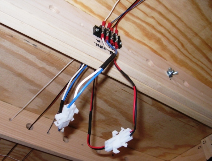
Shown below is the finished wiring of the left-hand module, including the power pack and turnout controllers. It shouldn’t be too hard to see the blue/white power bus running from left to right, several track feeder connections from that bus, and the red/black turnout control wiring for T1 on this module, T3 on the center module and T2 on the right module.
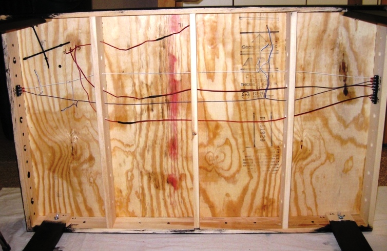
Compare this photo to the track planning diagram below. Looks pretty similar doesn’t it? That’s the idea – the actual wiring follows the planned wiring as much as possible. That makes it easy to wire now, and easy to debug later if a problem develops.

I didn’t photograph the underside of the center module; it follows the same general approach as the other two. But we’re not quite done yet. Even though the modules are wired, we still need to create the pigtail jumpers that will connect across the joints.
Building these takes a little work. It helps to have your wiring friend from the Club build these with you the first time. But once you get the hang of it, they go pretty quick.

Once you’ve built the blue/white track power jumpers, and the red/white turnout controller jumpers, all that’s left to do is install them. First you’ll need to place all the modules back on their legs and bolt the three sections together, of course. Then you’ll need to crawl under the layout with your jumpers and screw driver, hope your head doesn’t spin too much while looking up, and connect them to the screw-terminal strips.
The photo below shows the connections between the left and center modules. You can see track power, T2, and T3 turnout control.

The next photo below shows the connections between the center and right modules. You can see track power and T2 turnout control.
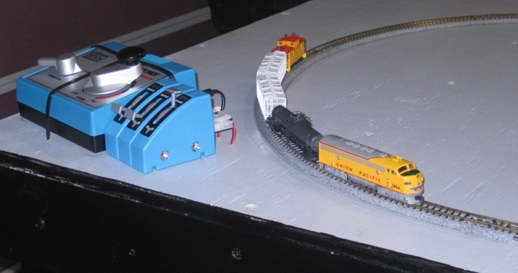
When it’s time to take the layout apart for moving, simply unplug the jumpers, un-bolt the layout sections, remove the legs, and away you go! But for now, it’s time to run trains …
Well that’s it – this project is finished for now. I hope you enjoyed following along. Perhaps you’ll try building your own sectional layout someday. Good luck and happy railroading! – Phil S.
