
My apologies – I haven’t posted progress since last December. Life has been pretty busy these past few months. I’ve been out-of-town traveling for work more than usual. I was gone two full weeks in January, another two in February, and another two in March. Now that April is upon us, my travel schedule has slowed down. I did manage to get some work done in-between trips, but it really hadn’t been until late March / early April that I’ve really had quality time with the project. So here we go …
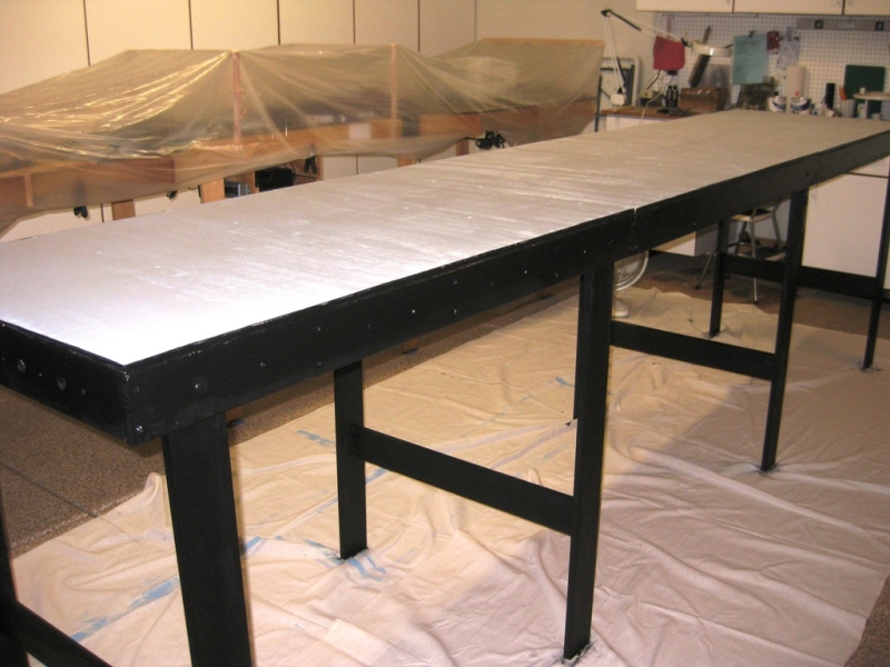
When we last saw our Sievers Benchwork, it was an open grid with legs. No top surface. No paint. As you can see in the photo below that has all changed. The top is half-inch plywood, one-side sanded and painted primer gray. The sides and legs are painted with several coats of semi-gloss black. It looks so different now. It’s amazing what a few coats of paint can do to make your benchwork look presentable and professional. And since this layout will be going on the road for displays and demonstrations, it needs to look good.
Enough about painting, let’s get to the fun stuff. Shown below is our selection of Kato track components, our train set, track and wiring diagrams, wiring pieces and parts, and a tube of silicon caulk to glue down the track.

Now we’re ready to lay the track, right? Wrong. We could start laying track, but we have to do so in a manner that supports our wiring needs. What?! Did he say wiring?! EEEEKKKK! Before you run and hide in the closet or under the bed, wiring isn’t difficult. In fact, it is one of the easiest parts of building a layout – if you make plan, follow that plan, and document your work. Kalmbach Books (publishers of Model Railroader magazine) have several good books on wiring. But frankly, Kato makes it so easy that you really don’t need a book – just some common sense and a little help from a friend. If you’re in a Club, someone there loves to wire (otherwise your trains would never run). Ask them for a little help. But first do some planning of your own. It will show them you are willing to do the work; and you’ll enjoy the achievement of having planned the work yourself.
First off, color coding is important. Choose reasonable colors for your wiring (not all the same color!) and document your choices, both during the planning stage and installation. Kato happens to use Blue and White for track power. In forward running mode, White is positive (+) and Blue is negative (-). For our layout I wanted the normal direction of the train to be such that it would “back in” to the stub siding making it easy to drop cars. That required counter-clockwise running. A little trial-and-error with some track and the power pack determined that I needed Blue connected to the inside rail and White to the outside rail so that the direction of the train match the direction switch labeling on the power pack.
For the turnout controllers, Kato uses Red and Black wiring. Frankly this seemed strange to me, as these colors are typically used for track power in a DC layout. But since the turnouts come pre-wired, I stayed with the Kato color coding.

In both of the above photos, you’ll note that Kato pre-terminates their wires with connectors. The intent is to make building and wiring a layout as easy as click-and-go. For the most part this is true, however in our case we needed longer wiring runs to reach turnouts and other terminal joiners (power feeders) across the layout. While Kato makes extension cables, they can be a bit pricy and require large holes be drilled for the connectors to pass through. As you’ll see later, I choose to cut the wires and splice in my own extensions (it just takes soldering skills) while still using the special Kato connectors at each end.
With this background, color-coding and specific use of wiring, I created the original wiring diagram (shown below). Looking at the left end you’ll note two terminal blocks, a blue one with terminals numbered 1-5 and white one numbered similarly. The intent was to create a power distribution point from which all terminal joiners would be powered. Let’s talk a little about power distribution. While it would be perfectly okay to hook up a single pair of power feeders from the Kato power pack to the track (and we do this all the time when setting up the circle of track around the Christmas tree), on a larger layout we run the risk of voltage drop at the far end of the layout, and we depend on every rail joiner to perform its dual role (both physical and electrical connectivity). So to ensure adequate power is available to the train no matter where it is located on the layout, I included power feeders TJ1 at the left end and a second set TJ5 at the far right.

But what about TJ3, TJ4, and TJ5 you might ask. Good question. Kato turnouts are “power routing” by design. That means only the track route selected by the turnout points receive power. In other words, when the mainline route (straight through the turnout) is selected, the diverging route (the curved part) is unpowered. So if a train is on the siding and the turnout leading to that siding is flipped back to the mainline, the train will stop due to lack of track power. This can be desirable in some track configurations, but in ours I didn’t want the feature. Unfortunately I can’t change the way the turnout is internally wired, but I can add extra power feeders to the siding. And that’s the purpose of TJ2 and TJ4 – to ensure the sidings always receive power. And TJ3 ensures the stretch of mainline between turnout T1 and T2 always receive power, regardless of the position of T1 and T2.
The turnout controller wiring is easy, just connect each turnout to its respective controller. All point-to-point wiring, no distribution blocks, no power issues, just plug-and-play. Well, except for the fact that the prewired turnouts aren’t long enough to reach from one end of the layout to the other, so we’ll need to splice those as discussed. But not yet.
Looking again at the diagram, note the dashed lines indicating the module joints. Since we need to take the layout apart to move it, we’ll need to provide connectors where the wires cross the joints. And the connectors we’ll be using have a Male and Female counterpart, noted as M and F on the plan. Notice the track power (Blue/White) has the Male on the left, while the turnout wiring (Red/Black) has the Female on the left. That’s done on purpose to prevent accidentally hooking the wrong connectors together during layout set up. Of course, the different wire colors should be the obvious clue to proper connections, but it helps if the connectors also protect you from making mistakes.
Okay, we’ve talked about this wiring diagram for a long time, but did you notice anything odd? What about all those blue/white wires going everywhere? Looks a bit complicated, doesn’t it? Looks like a waste of wire too. What about a different approach? What about a “power bus”? Below is the wiring diagram after a couple more revisions, the final one used for the layout.

Notice the removal of the track power distribution point (located at the left end on the original diagram). It has been replaced with a two-wire track power “bus” running the length of the layout. This bus distributes track power from one end to the other, making the connection of power feeders quick and easy. They only need to be long enough to extend from the track to the two-wire bus, instead of being routed all the way back to a central distribution point. This is very similar to the method used on Digital Command Control (DCC) layouts, and works equally as well for DC layouts.
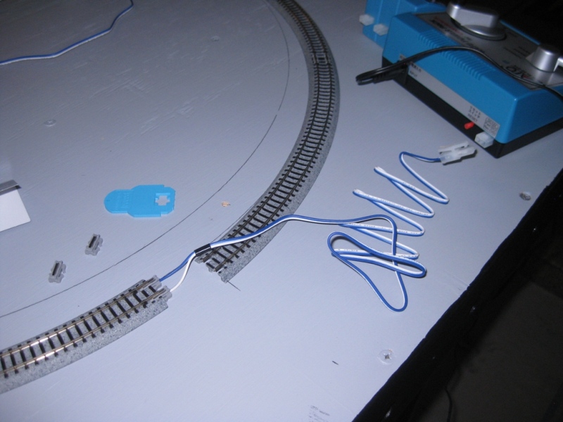
Now that we have our wiring planned, we know where each wire (power feeder and turnout control) needs to penetrate the plywood surface and get routed back to the power pack. And that’s important because we want to drill the holes under the track BEFORE we start laying the track. This enables us to hide all the wiring and gives a clean appearance. The closing photo for this installment shows the overall layout with the track placed (but not glued) temporary power connected to the track (so we can run trains) and the physical location of the power feeders (still in their packages).

It’s time for a break. Tune in again for our next installment, track laying. – Phil S.
